← All projects

Project 01 · Project Lead · May 2026 – Present

Project Oil Change: Fixed-Wing UAV for Autonomous Payload Delivery

Autonomous precision airdrop system — full-cycle design, manufacture, and structural testing of a fixed-wing UAV with GPS-guided payload release.

Role
Project Lead
Timeline
May 2026 – Present
Status
In build, pre-first-flight
Scope
Phase 1 of 2
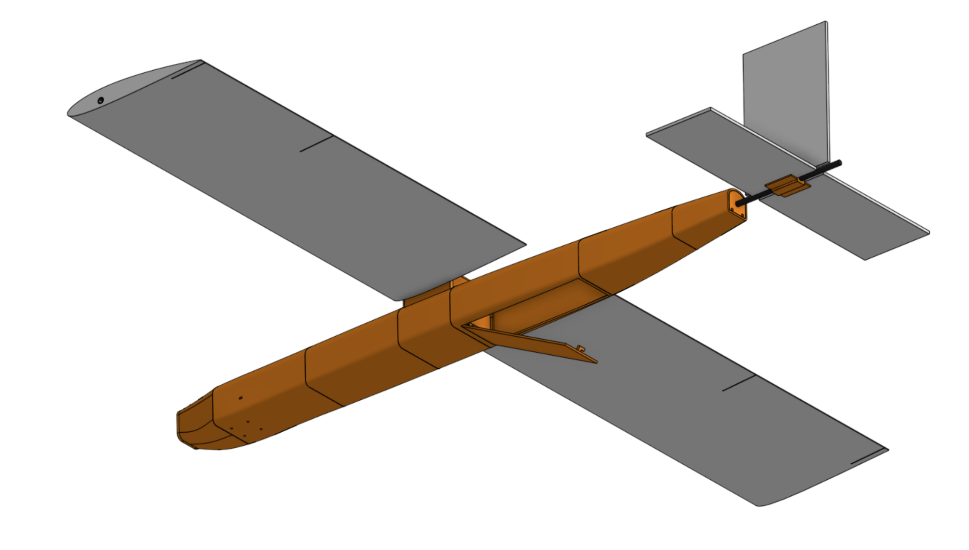
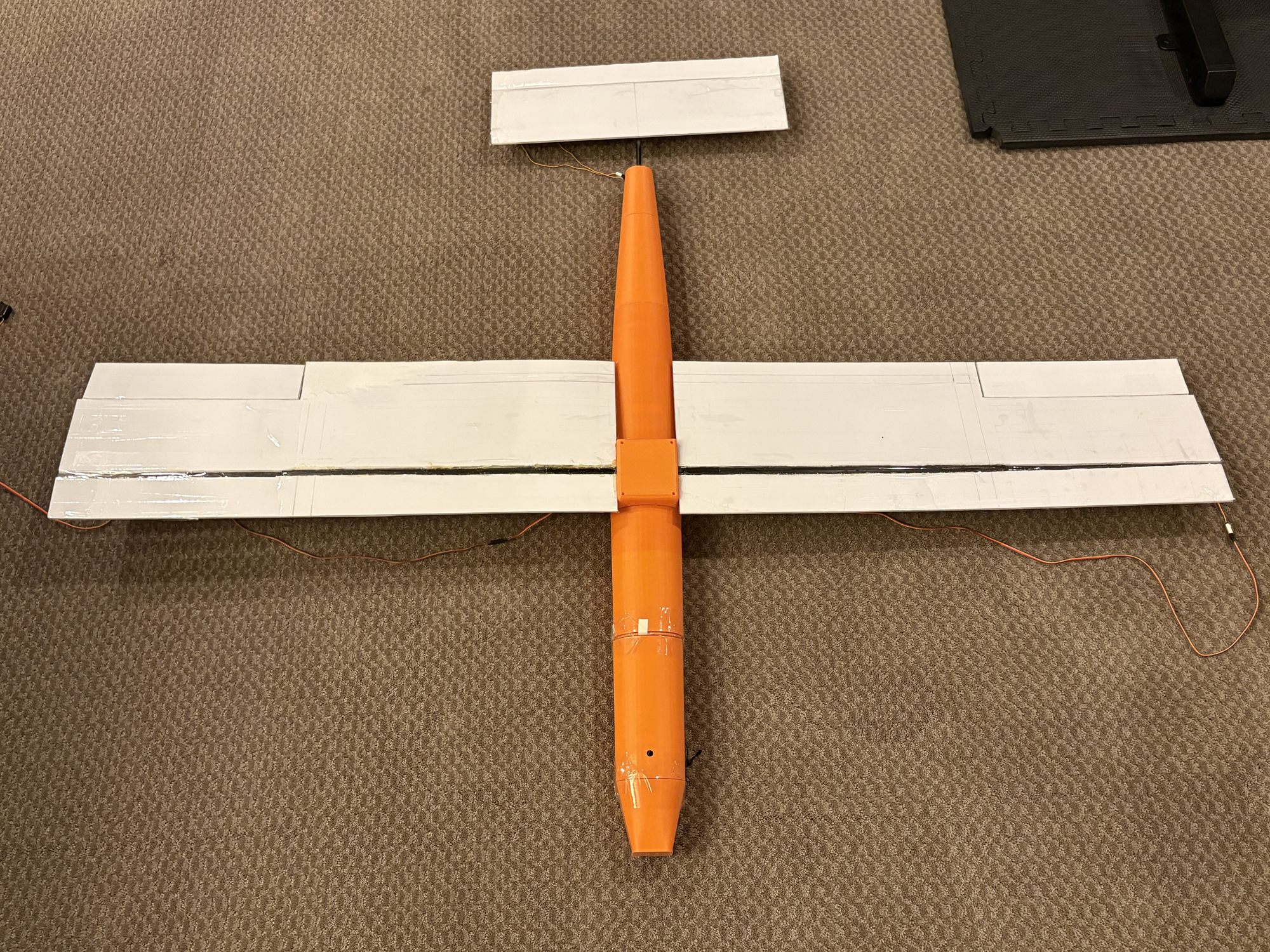
The assembled aircraft from above: printed fuselage, foam-board wings with the spar tube running spanwise, and the tail surface.
FIG. 01First iteration design, as built
01
Overview

An autonomous aircraft, sized and built from scratch, to fly a GPS route and drop a payload.

Built in two phases, so that terminal-guidance work sits on top of flight behavior that has already been validated.

Project Oil Change is a fixed-wing UAV I'm independently designing and building for autonomous GPS-guided navigation and a ballistic payload drop. It's architected in two phases: Phase 1 (current) covers GPS waypoint navigation and payload release; Phase 2 will add RF-beacon direction finding to improve landing precision beyond what GPS alone can deliver. The goal for Phase 1 is a fully self-contained aircraft, sized, designed, and built from scratch, ready to fly a GPS-defined route and release a payload on command.

2,100 g
MTOW (budgeted)
1,790 mm
Wingspan
17 m/s
Cruise
NACA 2412
Airfoil
02
What I did

I sized the aircraft off the mission requirements, then chose the airfoil against the cruise condition that sizing produced.

Each decision constrained the next one, so the order mattered as much as the individual choices.

01

Set nine mission requirements: a 500 g payload carried throughout, ~40 minutes of endurance, 15–20 m/s cruise, a 50–100 m drop altitude, 15 m drop accuracy, 3.0 kg maximum takeoff weight, 8 m/s wind tolerance, hand launch, and a belly landing on grass.

02

Built a component mass budget from comparable aircraft, including airframe, battery, avionics, servos, drop bay, which came to 2,100 g at maximum takeoff weight with the payload aboard.

03

Picked a wing loading of ~45 N/m², trading cruise efficiency against a stall speed I could still hand launch and belly land. That set wing area at 0.4578 m², and at aspect ratio 7 it gave a 1.79 m span on a 0.2557 m mean chord.

04

Those dimensions fixed the condition the airfoil had to work at: Re ≈ 294,258 at 17 m/s, Ncrit 6 for a foam wing flown outdoors, and a cruise CL of 0.2542 at maximum takeoff weight.

05

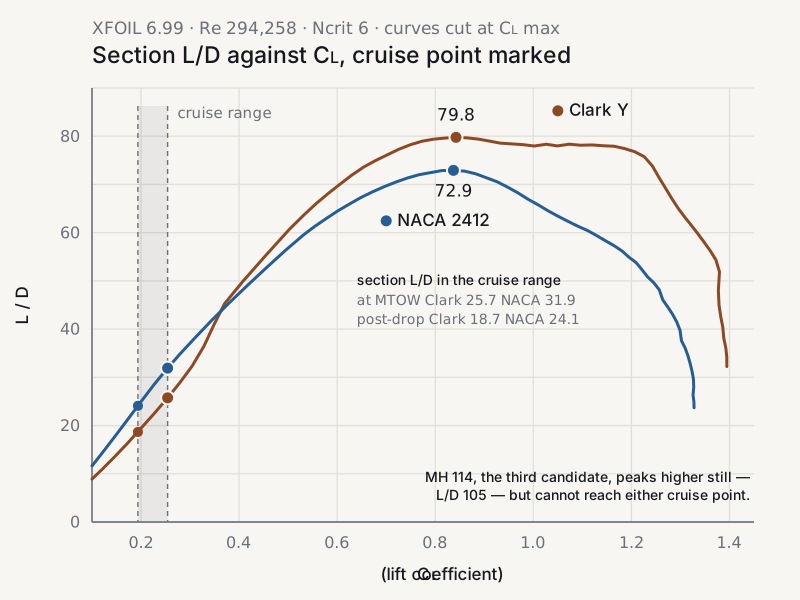
Compared NACA 2412, Clark Y and MH 114 at that cruise CL, all at the same Reynolds number. NACA 2412 gave the best section L/D of 31.9, compared to 25.7 for Clark Y, and sat at +0.27° of incidence where Clark Y needed −1.23° to hold the same lift. MH 114 has the highest peak L/D of the three at 105, but it never reaches the cruise condition at all: its lift doesn't fall below CL 0.287 anywhere in the sweep.

06

Checked the ranking again after the drop. Losing the 500 g payload takes cruise CL from 0.254 to 0.194 at the same speed, and the gap widens rather than closes (24.1 against 18.7) so the choice holds across the whole mission, not just the outbound leg.

07

Checked stall behavior: XFOIL puts CL max at 1.328 at α = 15°, and a 0.90 correction for low-Reynolds boundary layer effects brings the design value to 1.195. This yields a 7.84 m/s stall at maximum takeoff weight, and 6.84 m/s once the payload is gone.

08

Sized the tail surfaces by volume coefficient on a 0.767 m moment arm: 0.0610 m² horizontal at VH 0.40, 0.0374 m² vertical at VV 0.035, both NACA 0012.

09

Calculated induced drag against an Oswald efficiency of 0.839, plus parasitic drag from wing, fuselage and tails with a 10% miscellaneous margin. Total CD 0.0311, for an aircraft L/D of 8.17 at cruise.

10

Power and endurance calculations: 2.52 N of drag at cruise, 42.8 W of shaft power, 77.6 W electrical at 55% combined propeller and motor efficiency, 5.24 A draw. On a 4S 6000 mAh pack at 80% usable that is roughly 42 minutes, against the ~40 the mission asks for. Hand launch needs 1,380 g of static thrust to clear a 0.6 thrust-to-weight ratio.

11

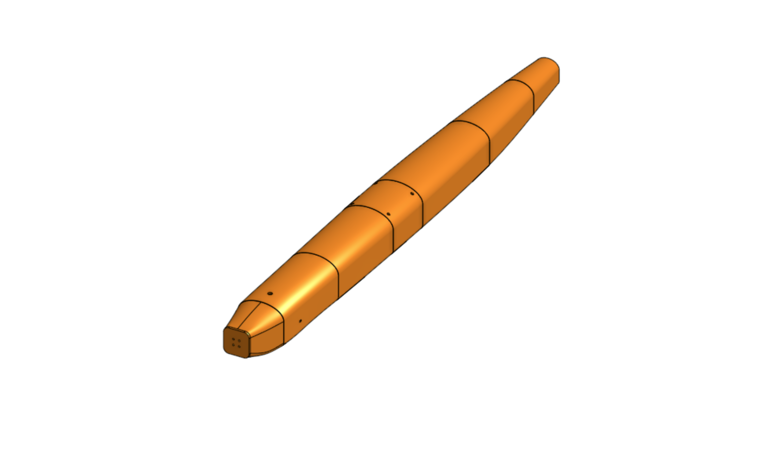
Designed the airframe in CAD as a seven-section PLA-printed fuselage, joined at 3–5 mm-thick formers for strength at each joint, built around a spar tunnel with foam-board wings.

12

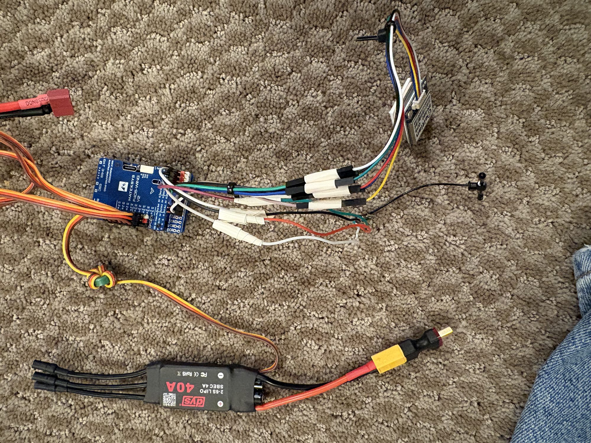
Selected and flashed avionics: a Matek F405-Wing V2 on ArduPlane with a Raspberry Pi Model 3 A+ for payload release logic, and servo/UART assignments mapped for the drop bay and reserved for Phase 2's beacon receiver.
Bottom view of the UAV airframe showing the fuselage sections
FIG. 02Airframe, bottom view — fuselage sections and spar tunnel
Section L/D against lift coefficient for Clark Y and NACA 2412, XFOIL at Re 294,258 and Ncrit 6. Across the cruise range NACA 2412 leads: 31.9 against 25.7 at maximum takeoff weight, and 24.1 against 18.7 after the payload drop, although Clark Y has the higher peak further right.
FIG. 03Airfoil selection — section L/D across the cruise range
CAD render of the fuselage, split into printed sections with the joint lines visible along its length.
FIG. 04Airframe design
The avionics laid out before installation: the Matek F405-Wing V2 flight controller, a GPS module, a 40 A ESC, and the servo and power harness.
FIG. 05Avionics integration
03
Tools & methods

What the work actually ran on.

Analysis, fabrication, and ground testing that brought the project from idea to reality.

Aero sizing
XFOIL — airfoil polars, CL/CD, L/D, stall behavior
Structures
CAD — fuselage, spar tunnel, wing geometry, structural analysis
Flight control
ArduPlane flashed onto a Matek F405-Wing V2, supplemented by a Beitian BN-880 GPS
Companion
Raspberry Pi — payload release logic
Fabrication
PLA 3D printing (fuselage sections), foam board (wings)
Ground testing
Flight controller calibration in Mission Planner; static wing loading test at maximum takeoff weight, Hardware in the Loop (HITL) testing of payload release logic and flight controls
04
What went wrong

What failed, and how to solve it.

Some flaws appeared during testing — some minor, others fatal. Here's how they were caught.

Failure 01Wing loading test

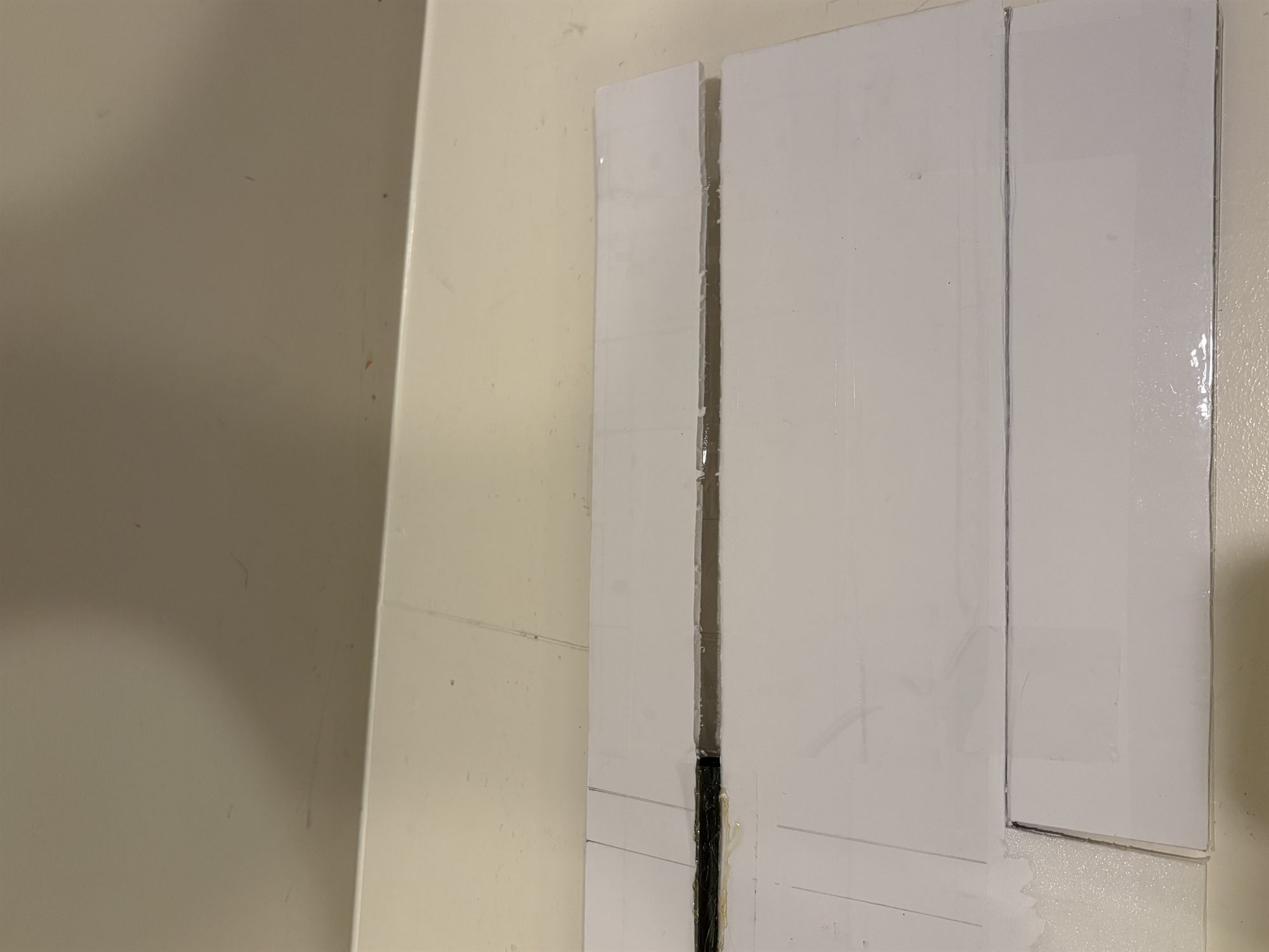
Spar tube didn't reach the wingtip

The tube stopped short of the full span, leaving the wingtips without structural support. As a result, they buckled and folded under load. Beyond the immediate failure, an unsupported tip like this is also more prone to flutter in flight, which would put ongoing vibrational stress on the foam board.

The fix

I wrapped the wing in packing tape as a temporary fix to complete the test, but that's not a real solution. The actual fix is a carbon fiber spar tube that runs the full span, paired with a tapered wing design. This allows for higher loading near the root, where the structure is strongest, and lower loading toward the tip, where it's weakest, all while keeping lift and drag performance close to the current design.

Failure 02Wing loading test

Spar tube tunnel wasn't secure against the fuselage

The tunnel sits on top of the fuselage as a separate attached part, and the tensile and shear loads it sees in flight could shear it off, especially without more robust fasteners.

The fix

Two fixes are on the table: moving the tunnel underneath the fuselage, where lift compresses it into the fuselage rather than pulling it away, or running the spar straight through the fuselage itself - removing the joint as a failure point entirely.

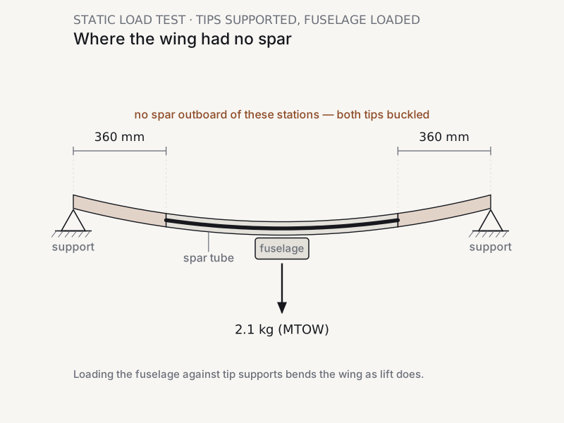
Diagram of the static load test: the wing supported at both tips with the fuselage loaded to 2.1 kg at the centre, bending the wing the way lift does. The spar tube stops 360 mm short of each tip, and those two unsupported bays are the sections that buckled.
FIG. 06Test setup — diagram
The spar tube in its channel along the foam-board wing, ending partway along and leaving the groove running on empty toward the wingtip.
FIG. 07Failure 01 — spar tube against full span
Failure 03Fuselage assembly

Joining method was permanent

I printed the fuselage in seven sections and planned to join them with CA or hot glue. In practice the sections didn't align perfectly, and glue made the joints permanent, which meant no way to reopen the airframe to charge the battery or access components.

The fix

Future iterations will use a mechanical joint instead: threaded sleeves, tongue-and-groove joints, or alignment pins, so the fuselage can be disassembled and reassembled as needed.

Failure 04Fuselage assembly

No internal access once assembled

With no hatches or access panels, there was barely room to work once the fuselage was assembled. Installing avionics, resetting the payload, charging the battery, and running hardware-in-the-loop tests were all difficult or impossible without pulling the airframe apart.

The fix

The fix is detachable, likely magnet-secured panels on the fuselage skin, which combined with a better joining method should make working inside the airframe far easier going forward.

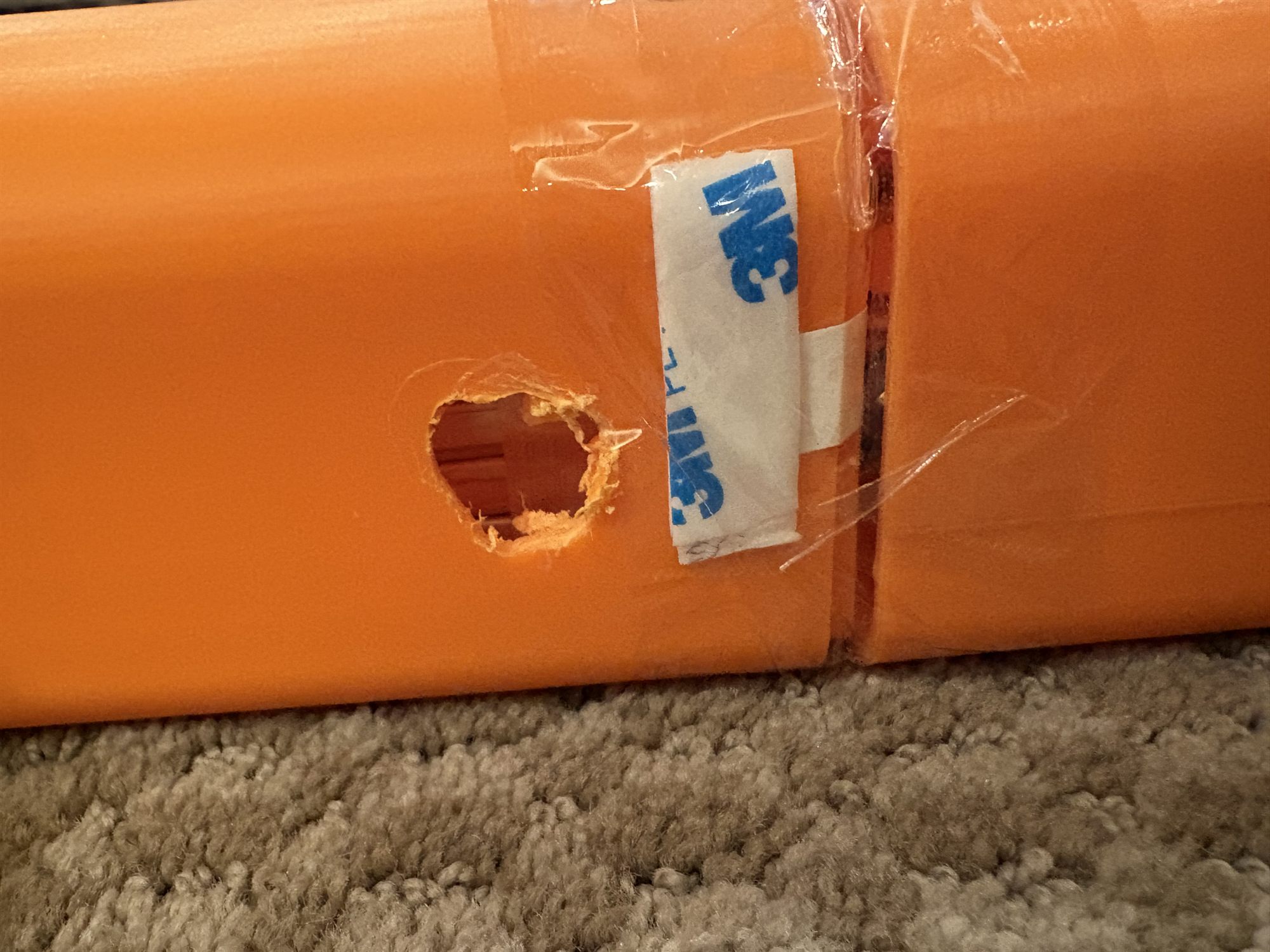
A ragged hole cut through the printed fuselage skin next to a taped section joint, the only way in once the airframe was glued shut.
FIG. 08Failures 03 and 04 — taped joint and the hole cut for access
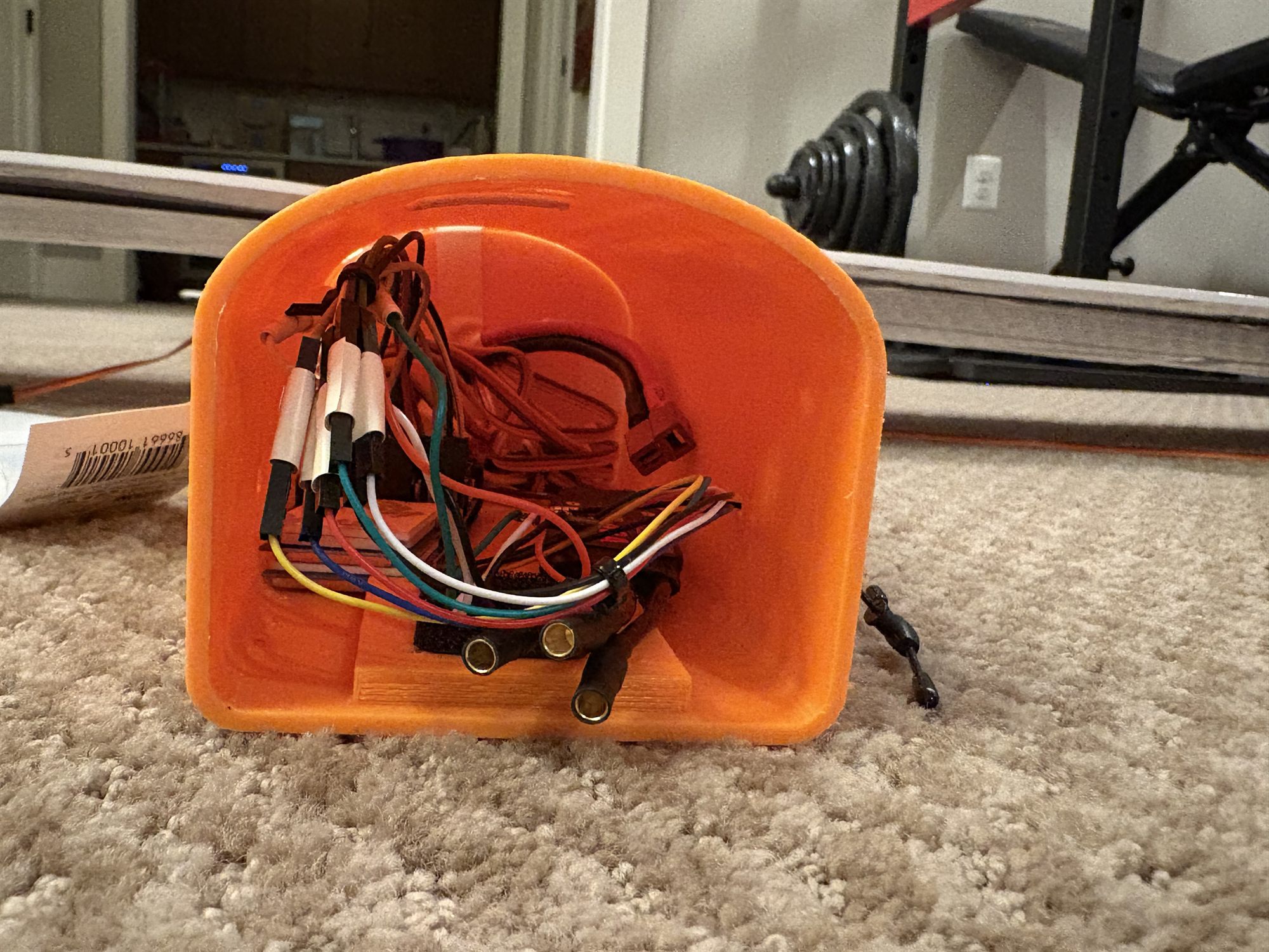
Looking into the assembled fuselage bay, packed with the wiring harness and connectors, with almost no room to reach inside once the sections are joined.
FIG. 09Failure 04 — the bay as built
05
What I learned

Three things I'd carry into the next airframe.

01

Loading a structure under actual weight is what finds design gaps CAD doesn't. The spar tube and tunnel issues were both invisible until the wing was under real load.

02

Structural margin has to be designed in at the geometry level (full-span support, tapered loading), not patched after the fact. Packing tape sufficed for the test, but it isn't a long-term fix.

03

Assembly and serviceability need to be designed in from the start, not retrofitted. A fuselage that's hard to open is hard to build, test, and maintain, regardless of how well the aerodynamics and structure are sized.

06
Next steps

The next iteration.

Phase 2 can't start until Phase 1 flight behavior is validated.

Source or manufacture a full-span carbon fiber spar tube and redesign the wing with a tapered loading profile.
Redesign the spar tube tunnel attachment, either relocated underneath the fuselage or routed through it, to solve the current failure point.
Redesign the fuselage joints around a mechanical (non-adhesive) connection method: threaded sleeves, tongue-and-groove, or alignment pins.
Add detachable, magnet-secured access panels to the fuselage skin for avionics, battery, and payload access.
After the structural fixes are in place comes the first flight test of Phase 1: GPS navigation and payload drop.
Phase 2: integrate RTL-SDR-based RF beacon detection for terminal-approach guidance, building on validated Phase 1 flight behavior.