← All projects

Project 03 · Duke AERO · August 2025 – Present

Payload Engineering: Guided Recovery, Camera Housing, and Descent Systems

Design, prototyping, and machining across four payload subsystems for a high-powered rocket.

Role
Payload Engineer
Team
Duke AERO · Payload sub-team
Timeline
August 2025 – Present
Status
2025–26 iteration complete
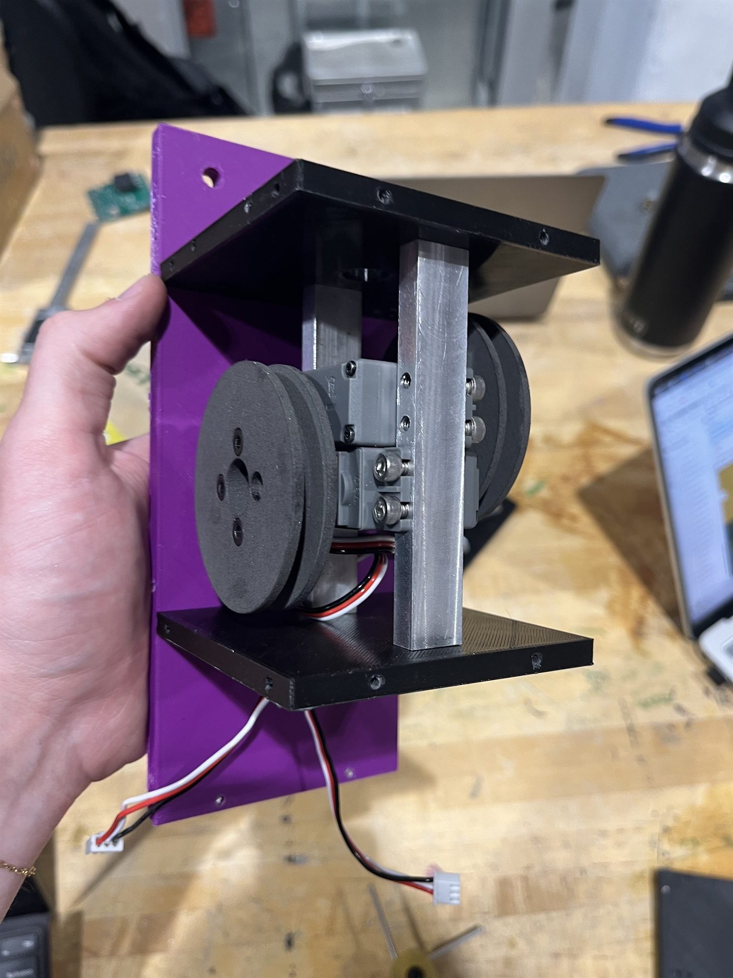
The guided recovery mechanism held in one hand: machined aluminum cross strut, black printed side plates, servo and pulleys mounted on a purple printed base plate.
FIG. 01Guided recovery mechanism, assembled
01
Overview

The payload that guided us to the podium.

A contributing role on a sub-team build, weighted toward the mechanical design work and manufacturing of key payload components.

I'm a Payload Engineer on Duke AERO's payload sub-team, contributing to the design and build of several components supporting the rocket's payload. My main work has been on the guided recovery system, redesigning the pulley mechanism that steers the parachute, and helping design the parachute itself, alongside the transparent camera housing and an energy recovery system that generates power from the payload's descent.

02
What I did

From diagnosing the problem to full system integration, here's how it went.

The guided recovery mechanism is the one that ran the full loop, from the inherited problem through to parts cut on a lathe.

01

Joined the payload sub-team and picked up work across three areas: the guided recovery mechanism, the transparent camera housing, and an energy recovery system for the descent phase.

02

Diagnosed the limitation in the previous year's guide-line mechanism: each rotation of the servo wasn't producing enough linear change in the parachute's guide lines to steer its trajectory reliably.

03

Debated between two candidate fixes, switching to continuous-rotation servos, or using a larger pulley radius on the servos already in use, and settled on using a larger radius.

04

Modeled the redesigned pulleys and their support struts in Onshape around the increased radius.

05

3D-printed FDM prototypes to check fit and range of motion before committing anything to metal.

06

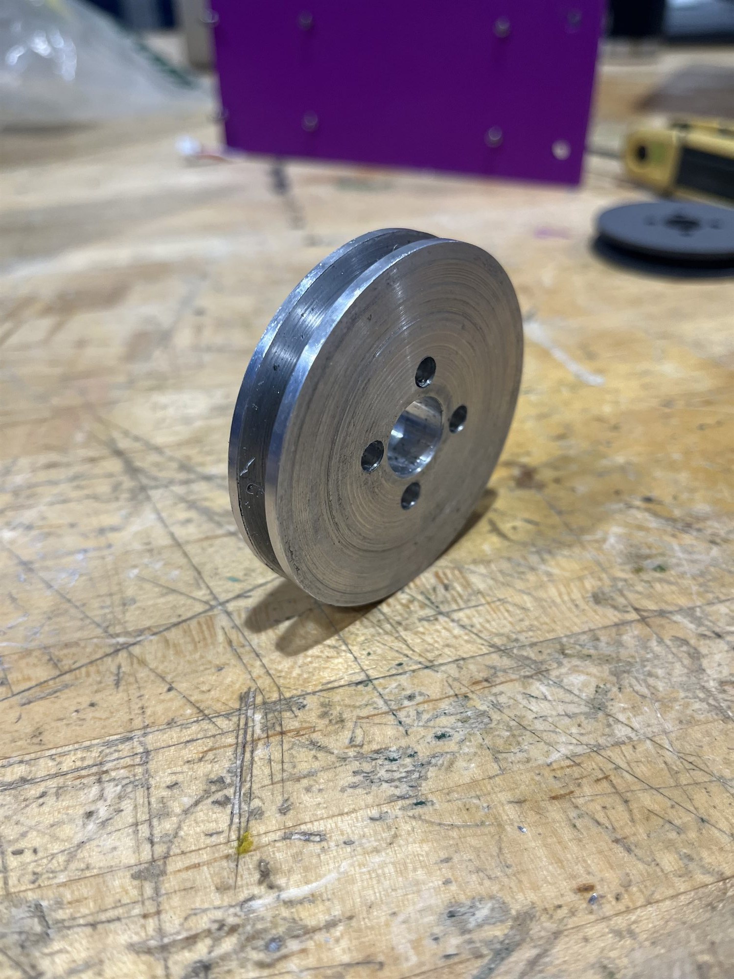
Machined the final parts from 6061 aluminum — pulleys turned on a manual lathe, support struts cut on a mill — and tapped threaded screw holes into the struts for assembly along the payload.

07

Helped design the cruciform parachute used in the final system.

08

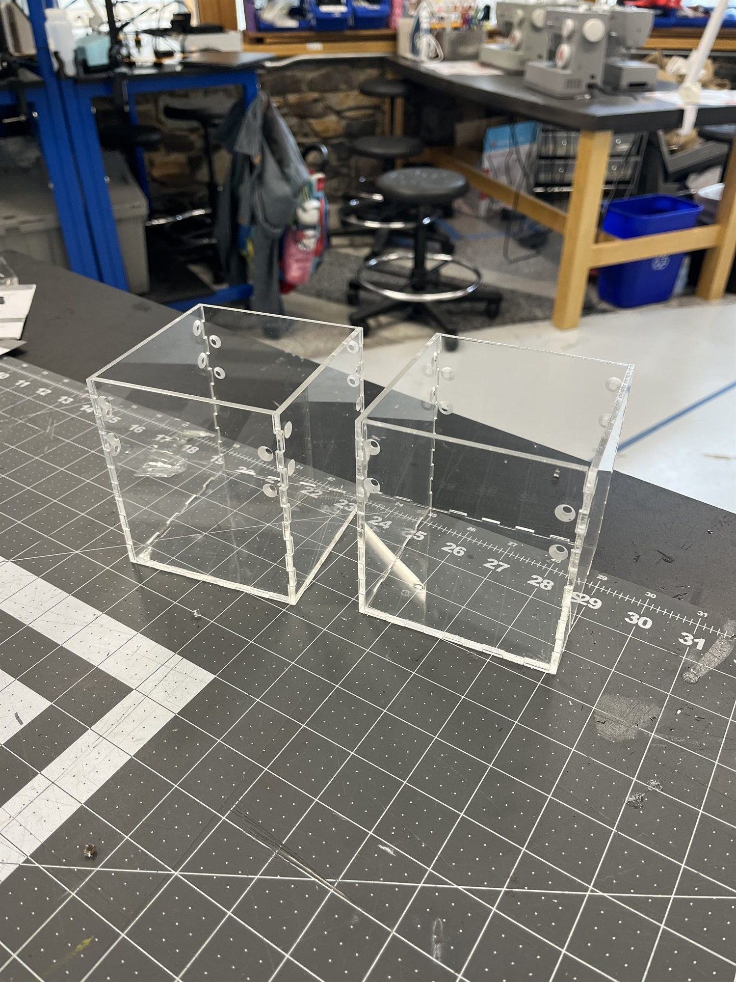
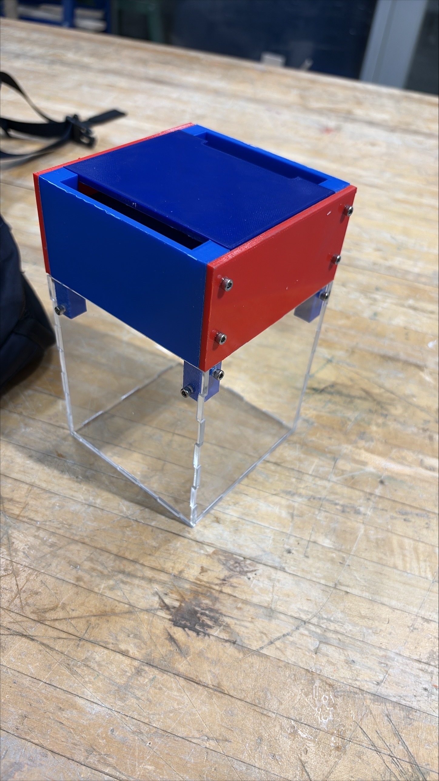
Prototyped the video camera's transparent housing in laser-cut acrylic, moved the final design to machined polycarbonate, and designed the full gimbal and camera enclosure used in the final payload.

09

Helped research and design an energy recovery system that generates power from drag-induced motion during the payload's descent.

A pulley turned from 6061 aluminum standing on a workbench, lathe tool marks visible across the face, with its V-groove and bolt circle.
FIG. 02Pulleys, as machined
Two laser-cut acrylic box housings standing on a cutting mat in the shop, bolt holes along their edges.
FIG. 03Camera housing prototypes, laser-cut acrylic
03
Tools & methods

The tools and machines I used.

A variety of software and hardware contributed to a precise and high-quality final product.

Design
Onshape — pulleys, support struts, gimbal and camera enclosure
Machining
Manual lathe (pulleys), mill (support struts), thread tapping
Prototyping
FDM 3D printing (mechanism prototypes), laser cutting (acrylic housing prototypes)
Materials
6061 aluminum (structural components), polycarbonate (final camera housing), acrylic (early prototypes), PLA (printed prototypes)
Testing
Initial payload drop test; vehicle launch
The gimbal and camera enclosure assembled: a red and blue printed frame bolted on top of a clear acrylic housing, standing on a workbench.
FIG. 04Gimbal and camera enclosure, assembled
04
The problem & the fix

Fixing the mistake from the previous year.

One major issue from last year that was vital to the performance and recovery of our payload.

The problemGuided recovery mechanism

Not enough linear travel per rotation to steer reliably

The previous year's guide-line mechanism had a real limitation: each rotation of the servo wasn't producing enough linear change in the parachute's guide lines to reliably steer its trajectory. The mechanism worked in the sense that it moved, but it just couldn't move the lines far enough to command a meaningful change in flight path.

The fix

Two fixes were on the table: switch to continuous-rotation servos, or increase the pulley radius to get more linear travel per rotation out of the servos already in use. Continuous servos were ruled out because they don't hold positional memory, so there'd be no way to return the mechanism to a repeatable neutral point; a steering system that can't find center is worse than one with limited throw. We went with the larger pulley radius instead, which I designed and manufactured along with the supporting struts.

FIG. 05Initial drop test
05
What I learned

A couple of trades worth considering.

01

Sizing a mechanism against real range-of-motion requirements, not just whether it technically actuates, is what separates a design that works on the bench from one that survives the trade-off analysis. Continuous servos looked like the simpler fix on paper, but would have sacrificed positional repeatability and could have made recovery more difficult.

02

Prototyping material and flight material don't have to be the same one. Acrylic was faster to prototype the camera housing with and more scratch resistant, but polycarbonate's strength was worth the added machining difficulty for the part that had to survive descent and protect the machinery within.

06
Where it stands

The 2025–26 design iteration is closed out, with a successful launch and recovery.

Duke AERO placed third in the 30K SRAD category at IREC 2026.

Guided recovery mechanism — redesigned around a larger pulley radius, machined from 6061 aluminum, and assembled onto the payload on tapped support struts.
Parachute — cruciform design, in the final system.
Camera housing — prototyped in laser-cut acrylic, final design machined from polycarbonate, with the full gimbal system safely enclosed within it.
Energy recovery — developed to generate power from drag-induced motion during the payload's descent.
FIG. 06Launch

To be continued into the 2026–27 design year